CNC Machined Parts
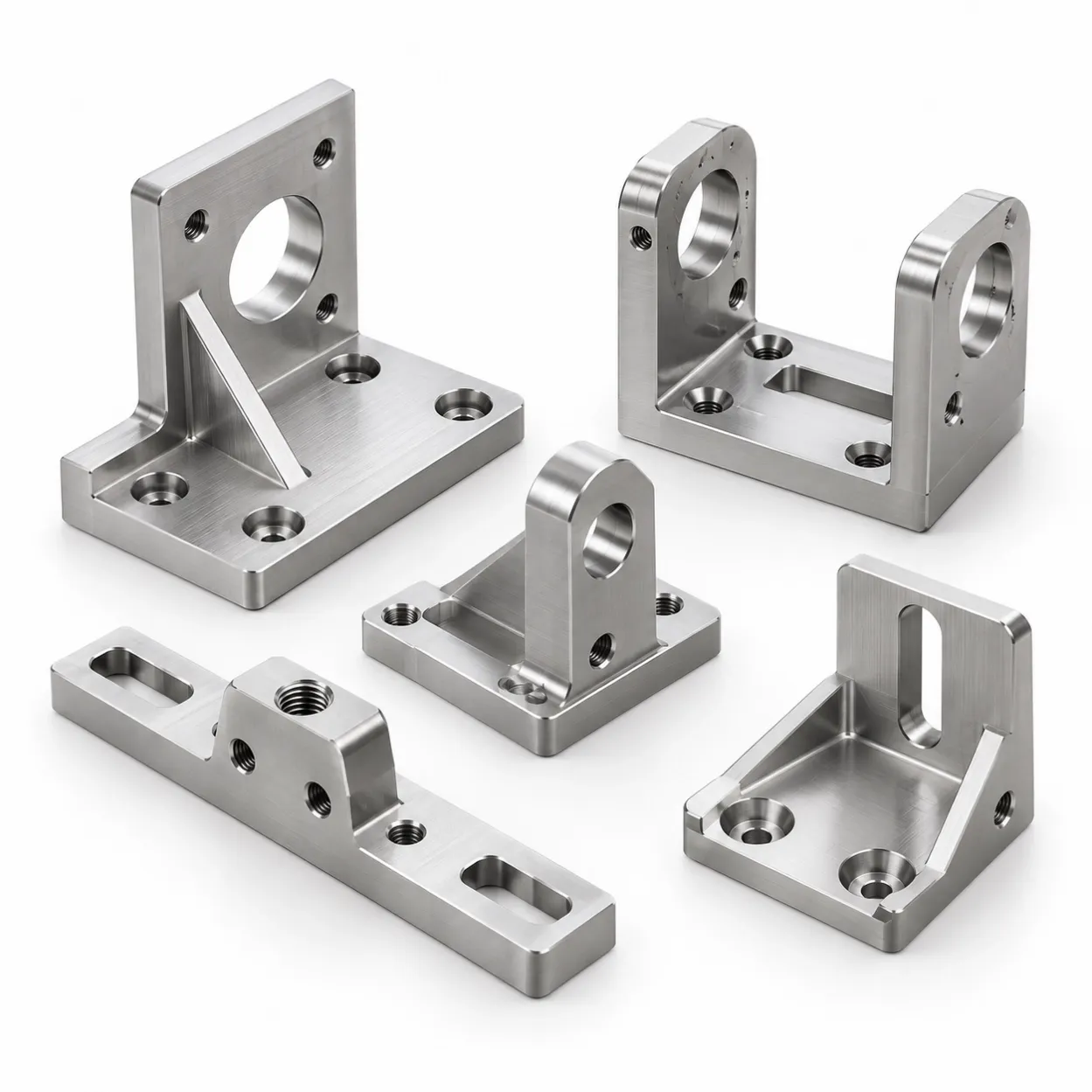
Custom CNC Machined Brackets
Custom CNC-machined brackets from approved drawings and CAD files in aluminum, steel, stainless steel and engineering plastics. Submit your RFQ for review.
YSBK manufactures custom CNC-machined brackets from customer-approved drawings and CAD files for industrial equipment, automation systems, tooling and engineering assemblies.
A description such as “custom bracket” is not sufficient for a production quotation. Submit the latest approved 2D drawing, matching STEP/STP file, exact material grade and the critical features that control fit, mounting and inspection.
CNC-Machined Brackets Made from Your Drawings
These brackets are manufactured to customer-defined geometry rather than selected from a standard catalogue.
Commonly reviewed component types include:
• equipment mounting brackets;
• motor, sensor and actuator brackets;
• structural support brackets;
• reinforced angle brackets;
• brackets with precision bores or bearing seats;
• brackets with pockets, slots and threaded holes;
• interface brackets joining two assemblies; and
• replacement brackets for industrial equipment.
YSBK manufactures the component against the approved file set. Material selection, design approval, load calculations and validation of the completed assembly remain the customer’s responsibility.
For projects controlled by released manufacturing files, see our guide to Build-to-Print Manufacturing.
Drawing and CAD Requirements
A STEP/STP model communicates nominal geometry, but it may not define the tolerances, datums, threads, finishes and inspection requirements needed for production.
Provide an approved 2D drawing, matching STEP/STP file, complete material specification and the functional requirements that control acceptance. If the drawing, CAD model, purchase order or written instructions conflict, the controlling requirement must be confirmed before production.
See 2D Drawing vs. 3D CAD for CNC Prototype Quotes for guidance on what each file should control.
Critical Features on a CNC Bracket Drawing
The functional relationships between bracket features are often more important than applying a tight tolerance to every dimension.
Mounting Faces and Datums
Identify the surfaces that locate the bracket within the assembly. If flatness, perpendicularity, parallelism or the relationship between two mounting faces is critical, define the requirement from an appropriate datum system.
The drawing should also state whether a dimension is inspected in the free state or under a specified holding condition.
Hole and Bore Positions
Mounting-hole patterns, precision bores, counterbores and mating features should be dimensioned from functional datums.
For critical locations, define the required positional tolerance rather than relying only on individual coordinate dimensions.
Threads and Fastener Features
Specify:
• thread standard and nominal size;
• pitch or threads per inch;
• internal or external thread class;
• full thread depth;
• blind-hole depth;
• counterbore or countersink requirements; and
• any required thread or fit inspection.
Thread requirements should not be inferred from the CAD model alone.
Pockets, Ribs and Thin Sections
Large pockets, thin walls, narrow ribs and extensive material removal may allow a bracket to move after it is released from the fixture.
Identify the dimensions that must remain controlled in the free state. Tight tolerances should be applied to functional features instead of every surface without distinction.
Materials Reviewed for CNC Brackets
CNC bracket projects may be reviewed in aluminum, carbon or alloy steel, stainless steel and engineering plastics.
Common material families already covered by YSBK’s dedicated product pages include:
• 6061-T6 and 7075-T6/T651 aluminum;
• 4140, 4140 PHT, A2 tool steel and carbon steel;
• 304/304L, 316/316L and 17-4 PH stainless steel; and
• POM/Acetal, PTFE and Nylon/PA engineering plastics.
Raw-material availability, stock size and supply feasibility must be confirmed for every order during the RFQ stage. YSBK will not substitute one material grade or condition for another without the customer’s written approval.
CNC-Machined Brackets vs. Sheet Metal Brackets
A CNC-machined bracket is generally reviewed when the design includes thick sections, precision bores, machined pockets, controlled mating faces, ribs or feature relationships that are produced from solid stock.
A formed sheet metal bracket follows a different manufacturing route involving cutting and bending. Bend radius, formed dimensions, sheet thickness and bend-related distortion must be considered separately.
If the component is primarily laser cut and bent from sheet, see Custom Sheet Metal Brackets.
If the component is mainly a flat machined base rather than a bracket, see Custom CNC Machined Mounting Plates.
Secondary Processes and Finishing
Depending on the material and drawing requirements, applicable anodizing, hard anodizing, passivation, black oxide, zinc or nickel plating, heat treatment, grinding, bead blasting, polishing, brushing, electropolishing, painting, powder coating and laser marking may be coordinated through subcontractors.
The appropriate process depends on the specified material and functional requirement. Feasibility, cost and lead time are evaluated for every RFQ. These secondary operations are not performed in-house and are not included automatically.
Coating thickness or material removal during finishing may affect holes, threads, fits and mating surfaces. The drawing should identify masking requirements and whether critical dimensions apply before or after finishing.
Inspection and Documentation
Basic dimensional verification uses calipers, micrometers, depth gauges and height gauges.
Inspection records cover only the critical dimensions agreed from the drawing. YSBK does not have in-house CMM or optical inspection equipment.
Full-dimensional reports and CMM reports are not provided by default. First-part photographs and key-dimension records must be requested and agreed during the RFQ stage.
Material certificates and lot or batch traceability documents are issued by raw-material suppliers. Certificate and traceability requirements must be confirmed for every order during RFQ and are not automatically included with shipment.
Prototype and Repeat Production
MOQ is one part. YSBK reviews one-off CNC brackets, engineering prototypes, replacement requirements and low-volume production batches.
For a first prototype, identify the production-intent material, critical mounting relationships and inspection points if the component may later proceed to repeat production.
Manual adjustments made during prototype assembly do not automatically become production requirements. Any approved change should be incorporated into the controlled drawing and matching CAD file before a repeat batch is released.
For early engineering evaluation, see Prototype CNC Machining. For released designs and small repeat batches, see Low-Volume CNC Machining.
What to Send for a CNC Bracket RFQ
Submit:
• approved 2D drawing;
• matching STEP/STP file;
• part number and current revision;
• complete material grade and condition;
• required quantities;
• mounting datums and mating-face requirements;
• critical hole, bore and slot locations;
• complete thread specifications;
• functional fits and tolerances;
• heat-treatment or hardness requirements, where applicable;
• finish, coating and masking requirements;
• inspection points and required records;
• certificate or traceability requirements;
• target delivery schedule; and
• confirmation of the file set that controls production.
If multiple brackets or related components belong to the same assembly, they may be submitted together. Identify the part number, revision and quantity for each component.
A complete RFQ package allows material availability, machining feasibility, subcontract requirements and inspection scope to be reviewed before quotation.
For additional preparation guidance, see CNC Machined Bracket RFQ Requirements.
Frequently Asked Questions
Can I order one custom CNC-machined bracket?
Yes. MOQ is one part, subject to drawing, material, geometry, finishing and inspection review.
Can you quote a bracket from only a STEP file?
A STEP/STP file can support geometry review, but it may not define tolerances, datums, threads, fits, material condition or inspection requirements. Provide an approved 2D drawing where these requirements apply.
What materials can be reviewed, and will YSBK substitute another grade?
Projects may be reviewed in aluminum, carbon and alloy steel, stainless steel and suitable engineering plastics. The exact grade, condition and stock size must be confirmed during RFQ. YSBK will not substitute another grade or condition without the customer’s written approval.
Does YSBK design complete bracket assemblies?
No. YSBK manufactures individual parts from customer-approved drawings and CAD files. Design approval, load analysis and validation of the complete assembly remain the customer’s responsibility.
Are finishing and heat-treatment processes performed in-house?
No. Applicable finishing, heat treatment and other approved secondary processes are coordinated through subcontractors. Feasibility, cost and lead time are evaluated for each RFQ.
What inspection records and material documents are included?
YSBK does not have in-house CMM or optical inspection equipment. Full-dimensional reports, CMM reports, first-part photographs and key-dimension records are not included by default. Material certificates and traceability documents are issued by raw-material suppliers. Any required records or documents must be agreed during RFQ.
Request a CNC Bracket Manufacturing Review
Send the approved drawing, STEP/STP file, material grade, quantity, mounting relationships, critical tolerances, finish and inspection requirements.
YSBK will review the submitted manufacturing information and identify any points requiring clarification before quotation.