Custom CNC Machined Mounting Plates
Custom CNC machined mounting plates and base plates with precision hole patterns, locating features and mounting surfaces. Made from drawings and CAD files.
YSBK manufactures custom CNC machined mounting plates and base plates from customer drawings and CAD files for industrial equipment, automation assemblies, tooling and custom machinery.
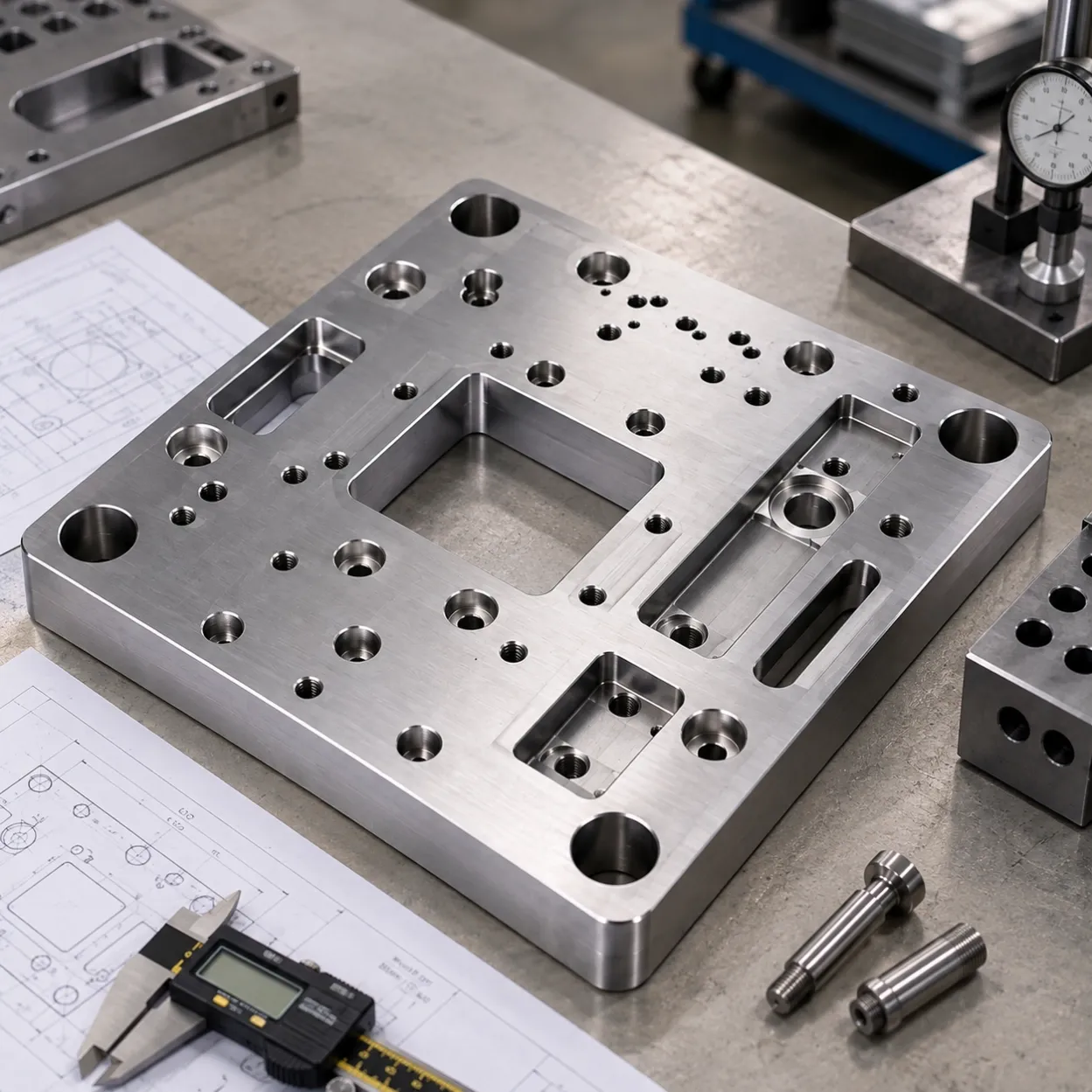
These parts are often more than simple flat plates. A typical machined plate may combine precision hole patterns, dowel or locating holes, counterbores, threaded holes, slots, pockets, stepped features and controlled mounting surfaces in a single component.
For mounting plates where several components must align through the same base, the relationship between holes, datums and mounting surfaces can be more important than any individual feature.
We support build-to-print prototype, one-off and low-volume projects based on released 2D drawings, 3D CAD or STEP files.
Have a mounting plate ready for manufacturing? Send your drawing or STEP file for review.
Precision Hole Patterns and Locating Features
Many mounting plates are used to position several mechanical components within the same assembly.
The manufacturing requirement is therefore not simply to machine a series of holes. The positions of those holes may need to remain controlled relative to locating features, datums and mounting surfaces defined on the drawing.
Typical features include:
- Precision mounting hole patterns
- Dowel and locating holes
- Reamed holes
- Counterbored holes
- Countersunk holes
- Tapped holes
- Clearance holes
- Mixed threaded and locating features
- Holes referenced to common datums
Where specified on the engineering drawing, critical feature positions can be inspected relative to the defined datum structure.
This is particularly relevant when a plate supports components such as linear guides, motors, actuators, sensors or other assemblies that must maintain a defined position relative to one another.
Mounting Surfaces and Critical Feature Relationships
A custom mounting plate often acts as the mechanical reference between several components.
For these parts, manufacturing review focuses on the relationships already defined in the customer's drawing, including:
- Hole patterns relative to mounting surfaces
- Dowel holes relative to threaded mounting positions
- Features referenced from a common datum
- Parallel or opposing mounting faces
- Component positions across stepped surfaces
- Locating features on different areas of the plate
- Mounting interfaces that control assembly alignment
This distinction matters because a plate can contain individually acceptable features and still create assembly problems if the required relationships between those features are not maintained.
YSBK manufactures these relationships according to the customer's released engineering documentation rather than redesigning the mounting system.
Slots, Pockets and Stepped Features
Industrial mounting plates frequently require more than drilling and tapping.
Depending on the drawing, CNC-machined features may include:
- Precision slots
- Recessed pockets
- Stepped surfaces
- Local mounting pads
- Relief areas
- Component clearances
- Machined cutouts
- Counterbored regions
- Reference edges and surfaces
These features may be used to establish component height, provide clearance, locate an assembly or create a defined interface between the plate and surrounding equipment.
For complex plates, the combination of these features is often what makes CNC machining more appropriate than a simple cut-and-drill process.
Custom Mounting Plates for Industrial Equipment and Automation
Typical applications include mounting and base plates for:
- Industrial equipment
- Automation assemblies
- Custom machinery
- Linear motion systems
- Motor and drive mounting
- Sensor mounting
- Actuator mounting
- Test and inspection equipment
- Machine modules
- Tooling and fixture assemblies
YSBK supplies the machined component according to customer drawings and CAD files.
Our role is manufacturing the defined mounting or base plate—not designing the complete automation system, machine or fixture.
Materials for CNC Machined Mounting Plates
Material selection should normally be defined by the application and engineering drawing.
Common options include:
Aluminum
- 6061
- 7075
- Other specified aluminum grades
Steel
- Carbon steels
- Alloy steels according to project requirements
Stainless Steel
- Common stainless grades according to drawing requirements
Aluminum is frequently used where weight, machinability or anodized finishing is important, while steel may be selected where stiffness, strength or wear resistance is more important.
We do not recommend selecting material from a generic online rule alone. The final material should reflect the load, environment, mounting requirements and existing engineering specification.
Surface Finishing
Depending on material and application, finishing requirements may include:
- Anodizing
- Hard anodizing
- Plating
- Black oxide
- Other specified surface treatments
For mounting plates with critical locating or mating interfaces, the drawing should identify any dimensions or surfaces whose finished condition affects assembly.
This helps the manufacturing review consider the component in its final finished condition, rather than treating machining and finishing as unrelated operations.
Inspection of Critical Mounting Features
Inspection should follow the functional requirements defined on the drawing.
Depending on the part, this may include verification of:
- Critical hole positions
- Locating and dowel features
- Hole diameters
- Threaded features
- Mounting surfaces
- Feature relationships
- Datum-referenced dimensions
- Other drawing-defined critical characteristics
The objective is not to apply the same inspection level to every dimension, but to verify the characteristics that matter to the component's intended assembly and function.
If your drawing identifies critical dimensions or inspection requirements, include them with the RFQ.
Prototype, One-Off and Low-Volume Projects
YSBK supports mounting plate projects for:
- Prototype equipment
- Engineering validation
- One-off machine builds
- Custom equipment
- Low-volume automation projects
- Small production batches
This is particularly suitable for engineering teams that already have a defined component and need a manufacturing supplier without committing to high-volume production.
We do not require a high production quantity to review a project.
What to Send for a Manufacturing Review
If your mounting plate is already designed, send the available engineering information with your RFQ.
Ideally include:
- 2D engineering drawing
- 3D CAD or STEP file
- Material specification
- Quantity
- Surface finish
- Critical tolerances
- Datum requirements
- Inspection requirements where applicable
The more clearly the functional requirements are defined, the easier it is to evaluate manufacturing requirements and prepare an accurate quotation.
Projects with an existing 2D drawing, 3D CAD model or STEP file are the best fit for our manufacturing process.
Request a Quote for Your Custom Mounting Plate
If you already have a custom mounting plate or base plate ready for manufacturing, send us the drawing or CAD file together with the material, quantity and critical requirements.
We can review the defined component for manufacturing and quotation.