Aug 30, 2026CNC Machining Guides
Mounting Plate Drawing Requirements for CNC Machining
Preparing a mounting plate drawing for CNC machining? Review hole patterns, locating features, datums, material, finish and critical requirements before requesting a quote.
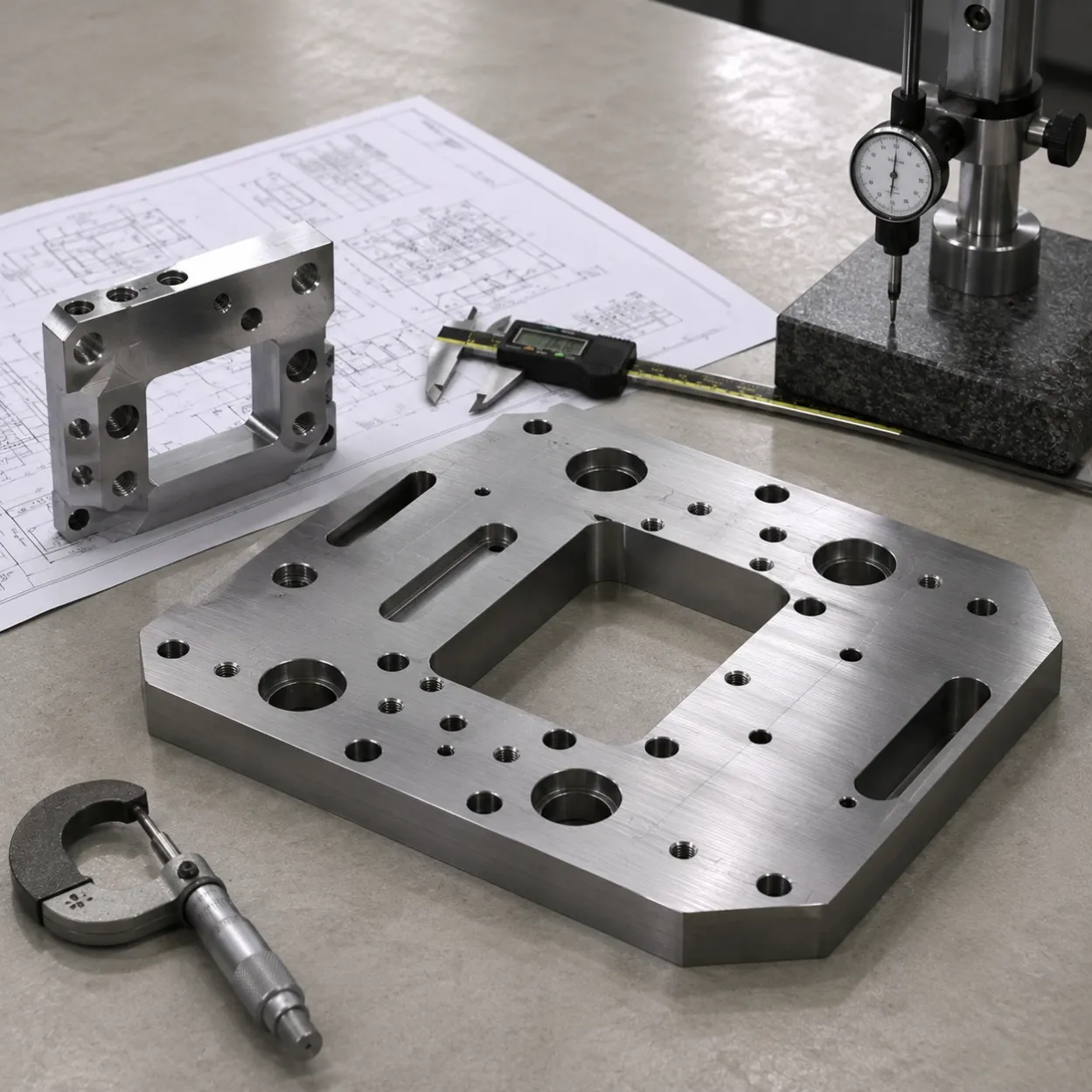
A mounting plate can look straightforward in CAD and still create questions when it reaches a CNC supplier.
The issue is usually not whether the basic geometry can be machined. It is whether the manufacturing information clearly defines the features that control how the plate will locate, support and align other components in the final assembly.
If your mounting plate is already designed and you are preparing a drawing for quotation, the goal is not to document every dimension with the same level of control. It is to make the functional requirements clear enough for the manufacturer to understand what matters, manufacture the part accordingly and quote without unnecessary assumptions.
For most custom mounting plate projects, that means providing the 3D geometry together with a drawing that clearly identifies critical holes, locating features, mounting interfaces, material, finish and any inspection requirements that affect function.
1. Use the 3D Model and 2D Drawing for Different Purposes
A STEP or other 3D CAD file gives the manufacturer the part geometry. For a mounting plate with pockets, slots, steps and multiple hole types, that model can remove a great deal of ambiguity.
But geometry alone does not always communicate engineering intent.
A 3D model may show where a hole exists without making it clear whether that hole is a general clearance feature, a precision locating hole or a critical mounting position. It may show a surface without identifying whether that surface establishes the position of another component.
A practical RFQ package therefore often includes both:
- A 3D CAD or STEP file defining the geometry
- A 2D drawing identifying material, critical dimensions, tolerances, threads, datums, finish and inspection requirements where applicable
The drawing does not need to duplicate every piece of information already contained in the model. It should add the manufacturing information that cannot safely be assumed from geometry alone.
2. Define Hole Types Clearly
Mounting plates often contain many holes, but those holes do not necessarily perform the same function.
A single plate may contain clearance holes for fasteners, tapped holes for component mounting, counterbores for recessed screw heads, dowel holes for repeatable location and other holes used for access or adjustment.
Before requesting a quote, check that the drawing distinguishes these features clearly.
For example, the manufacturer should be able to identify:
- Clearance holes
- Tapped holes and thread specifications
- Counterbores
- Countersinks
- Reamed holes
- Dowel or locating holes
This is particularly important when several similar-looking holes have different functional requirements.
The objective is not to add more notes than necessary. It is to prevent the manufacturer from having to infer the purpose or final condition of a feature.
3. Separate Locating Features From Fastener Features
This is one of the most useful distinctions to make on a mounting plate drawing.
Bolts and dowels may appear close together in the assembly, but they do different jobs.
Fasteners primarily clamp components together. Locating features establish repeatable position.
If a motor, actuator, sensor, linear guide or other component depends on dowel holes, locating bores, reference edges or another locating feature for alignment, that relationship should be visible in the engineering definition.
Otherwise, a supplier may see several holes with similar dimensions without knowing which ones actually control assembly position.
When reviewing the drawing, ask a simple question:
Which features determine where the mounted component actually sits?
Those features deserve clearer definition than non-critical clearance holes.
4. Make Critical Feature Relationships Clear
For many mounting plates, the difficult requirement is not the tolerance of one feature by itself. It is the relationship between several features.
A component may depend on the relationship between:
- Two locating holes
- A locating hole and a mounting surface
- A hole pattern and a reference edge
- A pocket and the holes used to mount the component inside it
- Features located on different areas or levels of the plate
If these relationships affect assembly, they should be understandable from the drawing.
This does not mean applying tight tolerances everywhere. In fact, doing so can make the drawing harder to interpret and may increase manufacturing cost without improving function.
Instead, identify the dimensions and relationships that actually protect fit, alignment or repeatability in the assembly.
5. Establish Useful Datum References
Datums are most useful when they reflect how the mounting plate functions or how important features relate to one another.
For example, a primary mounting surface may provide a logical reference for features controlling component height. A locating edge or bore may establish the position of a hole pattern.
The exact datum strategy depends on the assembly, so there is no single datum scheme that should be copied onto every mounting plate.
Before releasing the drawing, check whether the references make the critical relationships understandable.
A manufacturer should not have to guess which surface or feature establishes the functional reference for an important dimension.
For straightforward dimensions that do not affect assembly, a complex datum structure may add little value. The emphasis should remain on the relationships that matter to the finished part.
6. Define Pockets, Slots and Stepped Features Beyond Their Shape
A 3D model is especially useful for plates containing pockets, slots, relief areas and stepped surfaces.
However, some of these features may also have functional requirements that are not obvious from the model.
A recessed area may establish the height of a mounted component. A slot may provide adjustment rather than simple clearance. A machined step may form an interface with another assembly.
Where function depends on a particular depth, width, position or relationship, identify that requirement on the drawing.
Where the feature is simply clearance and does not require close control, avoid treating it as though it were a precision interface.
This distinction helps the supplier understand where manufacturing attention is actually required.
7. Apply Tight Tolerances Where They Protect Function
A mounting plate drawing does not become better simply because more dimensions have tight tolerances.
The useful question is:
What happens in the assembly if this dimension varies?
Dimensions associated with locating features, alignment, fits or critical mounting interfaces may require specific control.
Dimensions that provide generous clearance or do not affect component position may not.
A drawing that distinguishes between these two groups gives the manufacturer a much clearer picture of the part's functional requirements.
It can also reduce unnecessary cost.
When every feature is treated as equally critical, the supplier may have to quote additional machining and inspection effort that provides no practical benefit to the assembly.
8. Specify Material and Final Surface Condition
Material should be identified before quotation rather than left for the manufacturer to infer.
Depending on the project, the mounting plate may be made from aluminum, carbon or alloy steel, stainless steel or another specified material.
The RFQ should also identify required finishing such as anodizing, hard anodizing, plating or another specified treatment.
More importantly, consider whether finishing affects any critical interface.
For example, a locating or mating surface may have requirements that apply to the finished component rather than only to the machined condition.
If that distinction matters, state it clearly.
This gives the supplier a better basis for reviewing the complete manufacturing sequence rather than evaluating machining and finishing as unrelated operations.
9. Identify Inspection Requirements That Matter to the Assembly
Not every dimension requires a dedicated inspection report.
For prototype and low-volume mounting plates, it is more useful to identify the characteristics that genuinely affect assembly or performance.
Depending on the component, these may include:
- Critical hole positions
- Locating hole diameters
- Relationships between locating features
- Critical mounting surfaces
- Specific drawing-defined dimensions
- Other functional characteristics required by your quality process
If a dimensional report, material certificate or other project-specific documentation is required, include that information before quotation.
This allows the supplier to account for inspection requirements when reviewing the project rather than discovering them after manufacturing has started.
10. Include Quantity and Project Context With the RFQ
Quantity influences how a manufacturer evaluates a mounting plate project.
A one-off prototype, five engineering-validation parts and a recurring low-volume batch may use the same drawing, but they are not necessarily planned or quoted in the same way.
Include the expected quantity with the RFQ.
It can also be useful to briefly identify the part's role when that context explains a critical requirement—for example, whether the plate supports a linear motion assembly, positions sensors or actuators, or serves as the base for a machine module.
You do not need to provide the complete equipment design.
The objective is simply to give enough context to understand why the identified mounting and locating features matter.
Before Sending the Drawing for Quotation
A useful final review is to check whether a manufacturer receiving the files for the first time can answer the following questions without making major assumptions:
- What material is required?
- What quantity is required?
- Is the complete geometry available in CAD or STEP?
- Are the different hole types clearly defined?
- Which features locate components rather than simply fasten them?
- Which feature relationships are critical to assembly?
- Are important datums or reference features clear?
- Are critical mounting surfaces identified?
- Is the required finish specified?
- Are there inspection or documentation requirements that affect the quotation?
If these points are already defined, the project is usually in a much better position for manufacturing review.
You do not need to turn the drawing into a machining manual. The manufacturer needs a clear engineering definition of the finished component—not instructions on how to program or machine it.
Mounting Plate Ready for Manufacturing?
If your mounting plate is already defined in a 2D drawing, 3D CAD model or STEP file, YSBK can review it for build-to-print manufacturing and quotation.
Our focus is on manufacturing customer-defined parts rather than developing the complete machine, automation system or fixture from an initial concept.
For mounting plates with precision hole patterns, locating features, pockets, slots and critical mounting surfaces, see our Custom CNC Machined Mounting Plates manufacturing page.
Send your drawing or STEP file together with the material, quantity, finish and critical requirements for review.