Aug 30, 2026CNC Machining Guides
Machined Housing Design Considerations Before Requesting a Quote
Review key machined housing design considerations before RFQ, including tolerances, feature relationships, tool access, thin sections and finished interfaces.
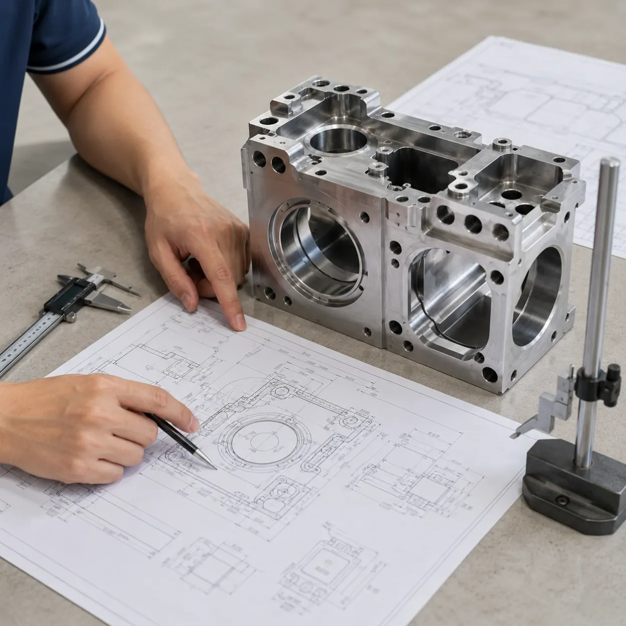
A machined housing can look complete in CAD and still generate avoidable questions when it reaches a manufacturer.
The issue is often not whether the part can be machined. It is whether the drawing clearly communicates which features control fit, alignment and assembly—and whether some design requirements create manufacturing complexity without adding functional value.
For engineers preparing a prototype or low-volume housing for quotation, a final design review can help separate what the assembly truly requires from what simply exists in the CAD model.
The following points are worth checking before releasing the drawing.
1. Apply Tight Tolerances Where They Protect Function
Not every dimension on a housing needs the same level of control.
A bearing location, locating feature or mating interface may require a close tolerance because a small variation could affect assembly or performance. A clearance pocket or non-functional exterior feature may have much more freedom.
Applying tight tolerances broadly can add manufacturing and inspection effort without improving the finished equipment.
Before tightening a dimension, ask:
What happens to the assembly if this dimension varies more?
If fit, alignment, sealing or equipment performance changes, the tolerance probably serves a functional purpose.
If nothing meaningful changes, it may not need the same control as a critical interface.
The objective is not simply to make tolerances wider. It is to make the drawing reflect the actual functional hierarchy of the housing.
2. Think About Relationships Between Features
Housing performance often depends on the relationship between several features rather than the size of one feature in isolation.
Consider two bearing locations supporting the same shaft. Both bore diameters can meet their individual size requirements while the assembly still has an alignment problem.
The same issue can appear between:
- a bore and a mounting reference;
- a locating feature and an adjoining component;
- mounting holes and a datum surface;
- features located on opposite sides of the housing.
When these relationships affect function, the drawing should communicate them deliberately rather than relying on the manufacturer to infer design intent from the CAD model.
This becomes increasingly important as more functions are integrated into a single housing.
3. Review Internal Geometry Before Releasing the Design
CAD makes deep cavities, narrow internal regions and complex transitions easy to create.
Physical access during manufacturing is different.
Before releasing the design, review whether difficult internal geometry exists because the equipment actually requires it.
Questions worth asking include:
- Does the cavity need its full depth?
- Does an internal feature need to extend into that location?
- Is a sharp internal transition functionally necessary?
- Are important surfaces difficult to reach because of surrounding geometry?
- Could a non-functional internal feature be simplified without changing the assembly?
There is no single pocket-depth or corner-radius rule that applies to every machined housing.
Material, overall size, access and surrounding geometry all matter.
The more useful question is:
Does this geometry exist because the assembly needs it, or because it was easy to create in CAD?
If the feature is functionally necessary, keep it and define it clearly. If it is not, reviewing it before RFQ may remove unnecessary manufacturing complexity.
4. Pay Attention to Critical Features Located on Different Faces
Many industrial housings contain machined features on several sides.
Multiple orientations are not automatically a problem. What matters more is whether critical features on different faces must maintain a precise relationship.
For example, a bore on one side may need to align with a mounting feature on another. An internal locating feature may need to reference an external mounting surface.
These relationships can influence how the housing is manufactured and verified.
Before releasing the drawing, identify cross-face relationships that affect the assembly and make sure the engineering definition communicates them clearly.
The goal is not to design the housing around a particular CNC machine.
It is to prevent an important functional relationship from being hidden inside the geometry.
5. Check Thin Sections Created by Large Internal Cavities
A housing machined from solid material may begin as a rigid block but finish with large cavities, thin walls and relatively flexible local sections.
That change in geometry deserves attention when precision features are located close to thin areas.
This is particularly relevant when a design combines large pockets with:
- thin exterior walls;
- isolated ribs or webs;
- significant differences in section thickness;
- precision bores near flexible regions;
- large amounts of material removal.
There is no universal minimum wall thickness suitable for every housing.
Instead, look at why the thin section exists.
If it is required for clearance, weight or another functional reason, it is a legitimate engineering constraint.
If it is simply a consequence of the CAD geometry, it may be worth reviewing before the drawing is released.
6. Consider the Finished Condition of Critical Interfaces
Finishing should be considered as part of the finished component rather than as an isolated operation added after machining.
This matters when treated surfaces interact with bearings, locating features, mating components, threads or other functional interfaces.
The useful design question is not simply:
Does this housing need a surface treatment?
It is:
Which interfaces still need to meet their functional requirements after finishing?
Where the finished condition matters to fit or assembly, the drawing should make that intent clear.
This reduces uncertainty when the manufacturer reviews the project and helps avoid assumptions about which surfaces are functionally important.
7. Do Not Over-Constrain an Engineering Prototype
Prototype housings sometimes carry requirements intended for a future production version before those requirements have been validated.
For an early prototype, the drawing should control what the engineering team actually needs to learn.
That may include:
- whether the housing fits the surrounding assembly;
- whether critical components align correctly;
- whether internal clearances are sufficient;
- whether mounting and locating features function as intended.
Those requirements matter.
Other dimensions may have little influence on the purpose of the prototype and may still change after testing.
This does not mean sending an incomplete design to the manufacturer.
There is an important difference between a defined prototype and an over-constrained prototype.
For low-volume engineering projects, preserving that distinction can make the first manufacturing cycle more useful and subsequent revisions easier.
Before Releasing the Housing for Quotation
A final drawing review does not need to turn into another design project.
Five questions can identify many of the issues that matter before manufacturing:
- Which dimensions actually control fit, alignment or function?
- Are any tolerances tighter than the application requires?
- Are difficult internal features functionally necessary?
- Do critical features on different faces have relationships that need to be controlled?
- Is the housing sufficiently defined for a manufacturer to evaluate without redesigning the part?
If the answer to the last question is yes, the project has moved beyond early design and is ready for manufacturing review.
That is the point where supplier feedback becomes useful—not to create the housing design, but to evaluate how an already defined component will be manufactured.
Ready for Manufacturing Review?
If your housing design is already defined and you have a 2D drawing, 3D CAD model or STEP file, you can move to the manufacturing stage.
Our Custom Machined Housings for Industrial Equipment page covers drawing-based manufacturing for prototype, one-off and low-volume housing projects.
If the project is ready, send the drawing together with the material, quantity and critical requirements for review.