Aug 26, 2026CNC Machining Guides
PEEK Machining Tolerances: How to Prevent Warping and Dimensional Changes
Learn what affects PEEK machining tolerances, why PEEK parts can warp or change dimensions, and how material grade, heat, geometry and annealing affect precision machined PEEK parts.
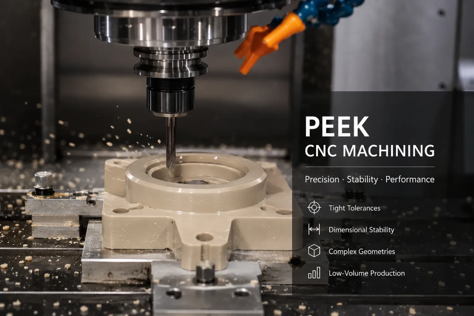
PEEK Machining Tolerances: How to Prevent Warping and Dimensional Changes
Custom PEEK machined parts are widely used in applications where engineers need a combination of mechanical strength, chemical resistance, electrical performance and elevated-temperature capability.
But specifying PEEK is only the first step.
A common challenge appears when a seemingly straightforward PEEK component requires tight tolerances, thin walls, precision bores, flatness, positional accuracy or complex geometry.
The part may machine correctly at first, but dimensions can move as material is removed or after the component is released from the fixture.
Why does this happen?
The answer usually involves a combination of material condition, internal stress, heat generated during machining, part geometry, fixturing and the tolerance strategy used on the drawing.
PEEK is considered a highly machinable engineering thermoplastic, but machining strategy still matters when dimensional stability becomes critical. Industry material guidance also identifies internal stress, heat input and geometry as important factors in maintaining dimensional stability during machining.
This guide explains what engineers should consider when designing or sourcing tight-tolerance CNC machined PEEK parts.
Why Can PEEK Parts Move During Machining?
Unlike metals, engineering thermoplastics can respond significantly to changes in temperature and internal stress.
PEEK stock material may contain residual stresses from previous manufacturing and thermal history. Machining removes material that was previously helping balance those stresses.
As material is removed, the remaining geometry may redistribute those stresses.
The result can be:
- Warping
- Bowing
- Flatness changes
- Bore movement
- Position changes
- Dimensional drift
- Distortion after unclamping
- Parts measuring differently after temperature stabilization
This does not mean PEEK cannot be machined accurately.
PEEK is commonly used for precision machined components and has good inherent dimensional stability. The challenge is understanding when the geometry and tolerance requirements require additional process control.
What Affects PEEK Machining Tolerances?
There is no single tolerance that should automatically be applied to every machined PEEK component.
The achievable tolerance depends on the complete part.
Important factors include:
- Part size
- Wall thickness
- Geometry
- PEEK grade
- Amount of material removed
- Machining sequence
- Fixturing strategy
- Cutting heat
- Critical feature location
- Inspection temperature
- Inspection method
- Final operating conditions
This is why an RFQ that simply states “PEEK, tight tolerance” does not provide enough information for a meaningful manufacturing review.
Critical dimensions should be identified clearly on the drawing.
1. Internal Stress Can Cause Dimensional Movement
One of the most important considerations when machining PEEK and other high-performance thermoplastics is residual stress.
Stress can originate from manufacturing of the raw material and can also be introduced during machining.
When significant amounts of material are removed—particularly from one side of a component—the internal stress balance can change.
The component may then move.
This becomes especially important for parts such as:
- Thin plates
- Large rings
- Housings
- Frames
- Components with large pockets
- Parts with deep cavities
- Long thin sections
- Asymmetrical components
Material suppliers specifically identify asymmetrical geometry, narrow sections, pockets, grooves and high one-sided stock removal as situations where warping risk deserves additional attention.
2. Heat During Machining Matters
PEEK should not simply be treated as aluminum or stainless steel with different cutting parameters.
Machining generates heat.
If excessive heat becomes concentrated around the cutting area, local thermal expansion can influence dimensional results.
Heat can also interact with residual stress in the material.
For precision PEEK components, the machining strategy therefore needs to consider:
- Cutting conditions
- Tool sharpness
- Heat dissipation
- Machining sequence
- Stock removal
- Part support
- Time between machining and final inspection
Ensinger's machining guidance emphasizes good heat dissipation and notes that localized overheating can contribute to dimensional changes in semi-crystalline thermoplastics.
This becomes increasingly important as tolerances become tighter.
3. Thin-Wall PEEK Parts Require Extra Attention
Thin walls are one of the geometries most likely to create difficulty in precision plastic machining.
Consider a PEEK housing with a large internal pocket.
Before machining, the stock is relatively rigid.
After most of the center material is removed, the remaining walls are significantly less rigid.
Cutting forces, clamping forces, internal stresses and temperature changes can therefore have a larger effect on the final geometry.
Potential problems include:
- Wall deflection
- Flatness changes
- Out-of-round bores
- Distortion after unclamping
- Position changes between features
For this reason, extremely tight tolerances should not automatically be applied to every wall and surface.
Instead, identify which dimensions actually affect assembly or function.
4. Asymmetrical Geometry Can Increase Warping Risk
Symmetrical material removal tends to produce a more balanced part than heavy machining from only one side.
Imagine two PEEK plates.
The first receives relatively equal machining on both faces.
The second begins as thick stock but has a deep pocket machined almost entirely from one side.
The second component generally presents a greater dimensional-stability challenge because the remaining material structure is less balanced.
For critical parts, a manufacturing strategy may therefore involve staged machining rather than immediately machining every feature to its final dimension.
5. Rough Machining and Finish Machining Can Be Separated
For demanding PEEK components, it may be useful to separate material removal into stages.
A simplified process may look like this:
Stock material → Rough machining → Stabilization / stress review → Finish machining → Inspection
During rough machining, most excess material is removed while leaving machining allowance on critical features.
The component can then be allowed to stabilize—or, where technically appropriate, undergo an intermediate stress-relief or annealing process—before critical dimensions are finished.
This approach is particularly relevant when the part includes:
- Tight tolerances
- Significant stock removal
- Thin sections
- Deep pockets
- Large flat surfaces
- Precision bores
- Complex asymmetrical geometry
Industry machining guidance likewise recommends considering intermediate annealing for critical geometries, narrow tolerances and high stock-removal situations.
Does PEEK Need Annealing Before Machining?
This is one of the most common questions engineers ask when sourcing precision PEEK parts.
The answer is:
Not every PEEK component requires an additional annealing operation.
For relatively simple components with normal dimensional requirements, properly conditioned stock and an appropriate machining process may be sufficient.
However, annealing or stress-relief should be evaluated when dimensional stability is especially important.
Examples can include:
- Tight-tolerance components
- Thin-wall parts
- Asymmetrical geometry
- Heavy material removal
- High-temperature applications
- Components showing movement during machining
- Precision features that must remain stable after machining
Annealing can reduce residual stresses and improve dimensional stability. Victrex also notes that machining can introduce stresses into PEEK components and describes annealing as a method for stress removal and dimensional stabilization.
However, annealing should not simply be added as a generic requirement to every PEEK drawing.
The appropriate thermal process depends on the specific PEEK grade, stock condition, geometry, application and material manufacturer's recommendations.
Why Final Machining After Stress Relief Can Matter
There is another important detail.
Annealing itself can result in dimensional change.
Therefore, if a component requires stress relief for dimensional stability, finishing all critical dimensions first and then annealing may not always be the best process sequence.
For certain precision components, a more appropriate sequence can be:
Rough machine → Stress relief / anneal → Finish critical dimensions → Final inspection
Victrex technical guidance specifically notes that when dimensional stability annealing is required for a machined component, it should be performed before the final machining step.
This is one reason the manufacturing process should be reviewed before production rather than treating heat treatment as an afterthought.
Unfilled vs Glass-Filled vs Carbon-Filled PEEK
Another common sourcing mistake is treating all PEEK as the same material.
It is not.
PEEK is available in numerous grades and formulations.
Three common categories are:
Unfilled PEEK
Unfilled PEEK provides the base properties of the polymer and is widely used for precision mechanical, electrical and industrial components.
It is often selected where engineers need a combination of:
- Mechanical properties
- Chemical resistance
- Temperature capability
- Electrical insulation
- Dimensional stability
Glass-Filled PEEK
Glass-fiber reinforcement can increase stiffness and change dimensional and mechanical behavior.
However, reinforced material also behaves differently during machining.
Tooling and machining strategy should therefore account for the specific grade rather than assuming the same process used for unfilled PEEK.
Carbon-Filled PEEK
Carbon-filled PEEK may be selected where additional stiffness, wear-related properties or other application-specific characteristics are required.
Again, the machining behavior differs from unfilled material.
Ensinger notes that unfilled, glass-filled and carbon-filled PEEK formulations respond differently to cutting forces and heat, making the exact material grade an important part of the machining plan.
Don't Specify Only “PEEK” on the Drawing
If material performance matters, writing only:
Material: PEEK
may not be enough.
Depending on the application, consider identifying:
- Unfilled or reinforced PEEK
- Required grade
- Manufacturer when required
- Color when relevant
- Electrical requirements
- Wear requirements
- Temperature requirements
- Material certification requirements
- Lot traceability requirements when applicable
This becomes especially important when the component is used in semiconductor equipment, scientific instruments, electrical systems, test equipment or other demanding industrial applications.
How Tight Can PEEK Machining Tolerances Be?
This is another question without a useful universal answer.
PEEK can be CNC machined into highly precise components, but the realistic tolerance should be evaluated against the geometry and functional requirement.
A small thick component with well-supported features behaves differently from a large thin plate with extensive pocketing.
Similarly, the tolerance achievable on a small precision bore does not automatically mean the same tolerance should be applied across a large overall dimension.
Instead of asking:
“What tolerance can you hold on PEEK?”
a more useful engineering question is:
“Which dimensions on this PEEK component are functionally critical, and what manufacturing strategy is required to control them?”
This changes the discussion from a generic machine capability question into a manufacturability question.
Avoid Over-Tolerancing Your PEEK Drawing
Over-tolerancing is a common source of unnecessary manufacturing cost.
For example, imagine a PEEK mounting component with 20 dimensions.
Only three dimensions affect:
- Alignment
- Assembly
- Fit
If all 20 dimensions receive the same very tight tolerance, manufacturing and inspection become more difficult without necessarily improving part performance.
A better drawing clearly distinguishes:
Critical dimensions
Features directly affecting fit, alignment or function.
General dimensions
Features where standard machining tolerances are acceptable.
Reference dimensions
Dimensions provided for information rather than manufacturing control.
This helps the manufacturer focus process control where it actually matters.
Temperature Should Be Considered During Inspection
Plastic dimensions are more sensitive to temperature than many engineers accustomed to metal components may expect.
If a PEEK part is machined at one temperature and inspected under substantially different conditions, dimensions may change.
For tight-tolerance parts, it is therefore useful to consider:
- Inspection environment
- Part stabilization before measurement
- Operating temperature
- Assembly temperature
- Critical fit conditions
This becomes particularly important when the component will eventually operate at elevated temperatures.
Common PEEK Machining Problems
When a machined PEEK component fails dimensional inspection, the root cause is not always the CNC machine itself.
Typical issues worth investigating include:
Warping After Machining
Possible contributors:
- Residual material stress
- Heavy one-sided stock removal
- Thin geometry
- Insufficient support
- Heat generated during machining
Dimensions Change After Unclamping
The fixture may have been holding the component in a slightly distorted condition.
After the clamping force is removed, the component relaxes.
Bore Becomes Out of Round
Thin surrounding walls or clamping forces may allow the geometry to move.
Flatness Changes After Pocketing
Removing a large amount of material from one side can alter the internal stress balance.
Dimensions Change During Service
Operating temperature, thermal cycling and residual stresses can affect the final dimensional condition of the component.
Victrex specifically notes that internal stress relaxation and post-crystallization at elevated service temperatures can result in dimensional changes, which is why thermal history should be considered for demanding applications.
Designing PEEK Parts for Better Machinability
Several drawing and design decisions can make PEEK components easier to manufacture consistently.
Identify Critical Dimensions
Do not make every feature equally critical.
Mark the dimensions that directly influence function, fit or assembly.
Avoid Extremely Thin Walls Unless Necessary
If thin walls are unavoidable, identify which surfaces and dimensions are most important.
Consider Material Removal
Large pockets and heavily asymmetrical stock removal deserve additional review.
Specify the Exact PEEK Grade
Especially when using reinforced or application-specific materials.
Provide Operating Conditions
Tell the manufacturer if the component will experience:
- Elevated temperature
- Thermal cycling
- Chemical exposure
- Electrical requirements
- Sliding or wear
- Vacuum conditions
These factors can influence material and manufacturing recommendations.
What Should You Send for a Tight-Tolerance PEEK Machining Quote?
A useful RFQ gives the manufacturer enough information to evaluate both machining and material requirements.
Whenever possible, provide:
- 2D drawing
- 3D CAD model
- Required PEEK grade
- Quantity
- Critical tolerances
- Precision fits
- Thread requirements
- Surface requirements
- Inspection requirements
- Material certification requirements
- Application or operating conditions
- Target delivery date
STEP or STP files together with a dimensioned PDF drawing are particularly useful.
The 3D model helps review geometry.
The drawing communicates tolerances, critical features and inspection requirements.
Example: A Thin-Wall PEEK Housing
Consider a PEEK housing machined from solid stock.
The component includes:
- A large central pocket
- Several precision mounting holes
- A thin outer wall
- One critical bore
- Flatness requirement on the mounting surface
The wrong approach is to treat every surface and dimension equally.
A better manufacturing review asks:
- Which bore controls assembly?
- Which mounting surface controls alignment?
- How much material must be removed?
- Is the remaining wall sufficiently rigid?
- Could clamping distort the housing?
- Should rough and finish machining be separated?
- Does the selected PEEK grade suit the application?
- Are inspection conditions defined?
Those questions are far more useful than simply asking whether the CNC machine can hold a certain number.
When Should You Request a DFM Review?
A manufacturability review is especially useful when your PEEK component includes:
- Tight positional tolerances
- Precision bores
- Thin walls
- Large pockets
- Large flat surfaces
- Deep cavities
- Complex geometry
- High material removal
- Reinforced PEEK
- Elevated operating temperatures
- Multiple critical fits
Reviewing these features before machining can reduce unnecessary tolerance requirements and help identify dimensional-stability risks earlier.
PEEK Machining Tolerances: Frequently Asked Questions
Can PEEK Be CNC Machined to Tight Tolerances?
Yes. PEEK is widely used for precision CNC machined components.
However, achievable tolerance depends on part size, geometry, wall thickness, material grade, machining strategy, thermal conditions and inspection requirements.
The drawing should therefore be reviewed rather than assuming one tolerance applies to every PEEK component.
Why Does PEEK Warp After Machining?
Common contributors include residual stress, excessive or uneven material removal, machining heat, thin-wall geometry and part fixturing.
Does PEEK Need to Be Annealed?
Not necessarily.
Simple parts with normal tolerance requirements may not require an additional annealing operation.
Annealing or intermediate stress relief becomes more relevant when dealing with tight tolerances, complex geometry, heavy stock removal or dimensional-stability requirements.
Is Glass-Filled PEEK Easier to Hold Tolerance Than Unfilled PEEK?
The answer depends on the grade and geometry.
Reinforcement changes stiffness, thermal behavior, residual stress and machining characteristics. Filled grades should therefore be evaluated according to the actual material specification rather than assuming they behave like unfilled PEEK.
Should Every Dimension on a PEEK Drawing Have a Tight Tolerance?
Usually not.
Critical functional dimensions should receive the appropriate tolerance, while non-critical features can often use reasonable general tolerances.
This can reduce machining complexity and inspection cost.
Need Help With a Tight-Tolerance PEEK Part?
If you already have a PEEK part drawing, send it to YSBK Parts for manufacturing review.
We can review your:
- Part geometry
- PEEK material requirement
- Critical tolerances
- Thin-wall features
- Precision fits
- Quantity
- Inspection requirements