Sep 5, 2026CNC Machining Guides
Build-to-Print Manufacturing: What Engineers Should Define Before Sending Drawings to a Supplier
Build-to-print manufacturing explained for engineers: what to define in drawings, CAD files, materials, tolerances, finishes and inspection requirements before supplier handoff.
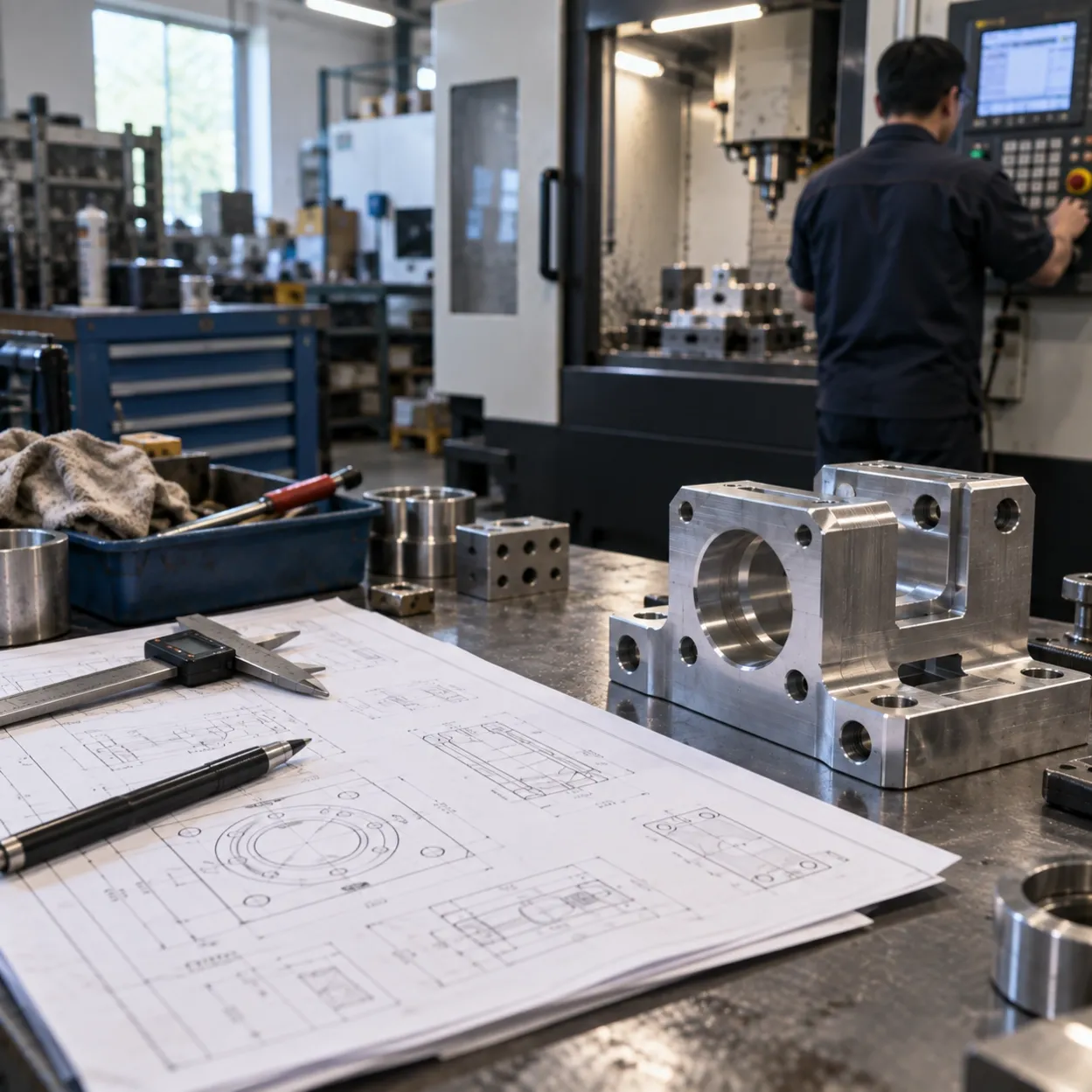
Build-to-print manufacturing starts when the design is already defined.
The customer provides the released drawings, 3D CAD files and manufacturing requirements. The supplier reviews the package, plans the manufacturing process and produces the parts according to those requirements.
The important point is that design authority remains with the customer. A manufacturing supplier may identify unclear or conflicting requirements, but that is different from taking responsibility for the product design.
For custom machinery, industrial equipment and engineering projects, the manufacturing package usually needs to define more than geometry. Material condition, tolerances, heat treatment, surface finish and inspection requirements can all affect how a part is quoted and produced.
What Is Build-to-Print Manufacturing?
Build-to-print is a manufacturing arrangement in which parts or assemblies are produced according to customer-controlled engineering documentation.
A typical manufacturing package may include:
- 2D engineering drawings
- 3D CAD or STEP files
- Material specifications
- Dimensions and tolerances
- Heat treatment or hardness requirements
- Surface finishing requirements
- Inspection requirements
- Quantity
The supplier's role is primarily manufacturing execution: reviewing the requirements, sourcing the specified material, planning the required processes, manufacturing the parts and verifying them against the agreed specifications.
This model is particularly relevant when the engineering team has completed the design and needs manufacturing capacity rather than additional product development work.
It can apply to one custom component, a small set of machine parts or multiple drawing numbers belonging to the same equipment project.
Build-to-Print vs. Build-to-Spec
The main difference is who controls the design.
Build-to-Print | Build-to-Spec |
|---|---|
Customer provides the completed design | Customer defines functional or performance requirements |
Supplier manufactures to released drawings and specifications | Supplier may develop or modify the design |
Customer retains design authority | Supplier has greater design responsibility |
Design changes normally require customer approval | Supplier may determine how requirements are achieved |
For example, an engineering team may already have completed the design of a fixture, housing, mounting plate or other machine component.
If the supplier receives the released drawing and manufactures the component accordingly, the work is essentially build-to-print.
If the customer instead provides functional, dimensional or performance requirements and expects the supplier to develop the component design, the responsibility is different.
This distinction should be clear before quotation.
Manufacturing review is not the same as assuming responsibility for the customer's engineering design.
What Should Be Defined Before Sending Drawings to a Supplier?
A finished 3D model does not necessarily contain everything required to manufacture a finished part.
Before releasing the manufacturing package, check the information that affects quotation, process planning and inspection.
Drawing and CAD Revision
The supplier should be able to identify the current release without guessing.
Part number, drawing revision and CAD revision should be consistent, especially when several components belong to the same machine or assembly.
Material Specification
Specify the material and condition required for the finished component.
For some alloys and engineering materials, the general material designation alone may not fully define the manufacturing requirement. Temper, hardness or pre-hardened condition should be specified where they affect machining or final part requirements.
Critical Dimensions and Tolerances
Not every dimension requires the same level of control.
Identify the features that matter to assembly or function, such as:
- Fits
- Bearing seats
- Hole locations
- Alignment features
- Mating surfaces
- Critical thicknesses
- Tight positional requirements
This helps the supplier understand where tighter manufacturing and inspection control is required.
Heat Treatment and Hardness
If the finished component requires heat treatment, define the required condition and hardness.
Where the manufacturing sequence matters, specify that as well.
Heat treatment requirements can affect machining strategy, stock allowance, secondary operations and final inspection. They should therefore be considered as part of the manufacturing definition rather than as an isolated note.
Surface Finish and Secondary Processes
Geometry is only part of the finished requirement.
Depending on the component, the manufacturing package may also specify:
- Deburring
- Grinding
- Anodizing
- Black oxide
- Plating
- Painting
- Welding
- Polishing
Make clear which requirements apply to each part.
Quantity
Quantity affects process planning even when the design is unchanged.
Custom machinery and industrial equipment projects are not necessarily high-volume. A project may require a one-off component, several matched parts or a small production batch.
Providing the expected quantity at the quotation stage helps the supplier evaluate an appropriate manufacturing approach.
Keep Drawings, CAD Files and Revisions Aligned
When both a 2D drawing and a 3D CAD model are supplied, each file has a different role.
The 3D model communicates geometry efficiently. The drawing can contain manufacturing information that may not be fully represented in the model, including tolerances, threads, finishes, hardness, inspection notes and other requirements.
Before supplier handoff, verify:
- Part numbers match
- Drawing and CAD revisions correspond
- Superseded files have been removed
- Drawing dimensions and model geometry do not conflict
- Notes refer to the current design
- The correct STEP/STP files are included
For projects containing multiple drawing numbers, a simple parts list can also help keep quantities and revisions clear.
The objective is straightforward:
The supplier should not have to decide which version represents the released design.
Geometry Alone Is Not a Complete Manufacturing Definition
A STEP file can describe the geometry of a component very well.
It does not necessarily define the finished manufacturing requirement.
Two components can have equally complete 3D models but require very different manufacturing routes. One may require a controlled material condition and secondary finishing, while another may require heat treatment, tighter inspection or a different surface treatment.
The CAD model defines the geometry. The released manufacturing package defines what the finished part must be.
This becomes particularly important in multi-part equipment projects, where different components may require different materials, manufacturing processes and secondary operations.
The supplier needs those requirements before the parts move through production.
Requirements Worth Checking Before Release
Before sending a project for quotation, review the areas that may otherwise require clarification later.
Revision Consistency
Confirm that the drawing, CAD model and parts list refer to the same release.
Material Condition
Do not rely on a broad material family when temper, hardness or material condition affects the finished component.
Critical Tolerances
Make functional and inspection-critical dimensions identifiable rather than applying unnecessary tight tolerances everywhere.
Heat-Treatment Sequence
Where dimensions or other requirements depend on the sequence of machining and heat treatment, make the required condition clear.
Finishing Requirements
Specify the required finishing process and any relevant areas that require special treatment or exclusion.
Inspection Requirements
Identify features requiring specific inspection or additional documentation.
Quantity and Project Grouping
For projects containing multiple drawing numbers, provide quantities by part number and indicate which components belong to the same assembly or project where useful.
These details do not change the design. They make the released manufacturing package easier to quote, plan and inspect correctly.
Build-to-Print RFQ Checklist
A practical RFQ package for drawing-based custom parts normally includes:
Information | What to Provide |
|---|---|
2D Drawing | Current released drawing and revision |
3D CAD | STEP/STP or other agreed manufacturing model |
Part Number | Clear identification for each component |
Material | Material and required condition |
Quantity | Required quantity for each part number |
Tolerances | General and critical tolerances |
Heat Treatment | Required process, condition or hardness |
Surface Finish | Required finishing and secondary processes |
Inspection | Critical features or documentation requirements |
Delivery | Required delivery date or project schedule |
For a multi-part project, adding a simple BOM or parts list can make the quotation process easier to manage.
Ready for Manufacturing Review?
If your design is complete and you already have 2D drawings and 3D CAD/STEP files, the next step is a manufacturing review.
YSBK Parts supports custom CNC machining from customer drawings for prototype, low-volume and engineering project components, including coordination of required secondary processes and finishing.
If your drawings and CAD files are ready, send us your project requirements for manufacturing review.