CNC Machining Guides
Sheet Metal Bending DFM: Flange Lengths, Hole-to-Bend Distance and Reliefs
The bending design review in drawing order — minimum flange lengths, holes out of the deformation zone, corner reliefs and bend radii — with the honest note on when each rule can be paid around.
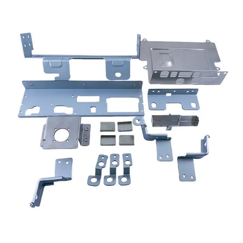
Bent sheet metal parts fail their first quote for the same three reasons: a flange too short for the tool, a hole sitting in the deformation zone of a bend, and a corner that has no relief. None of these are hard to fix — on the screen. In the shop they mean re-cutting, re-bending, or a hand correction charged as "additional work". This review takes your bent part in the order you would draw it: the flanges, then the holes, then the corners — with the standard practice for each and the honest note of when the rule can be bent back.
The flange: short enough to bend, long enough to hold
Every flange needs a minimum length for the tooling to grip during the bend — shorter than that and the bend simply cannot be made on standard tooling, or the flange twists instead of forming. The exact minimum depends on the thickness and the die, so state your flange lengths and let the fabricator confirm against their tooling; the practical move is designing flanges long enough to be standard, and flagging any short flange deliberately. At the other end, very long flanges on thin material can bow or wave after bending — a long flange may want a relief slit or a stiffer thickness rather than more length.
Holes and the bend: the deformation zone
The metal within roughly two to three thicknesses of a bend gets stretched and disturbed as the bend forms. A hole punched inside that zone distorts into an oval; a slot near a bend closes up. The standard practice: keep holes out of the bend zone, or cut them after bending (functional, quoted as a second operation). If a hole must sit close to a bend, say so on the drawing and accept either a slight distortion allowance or the post-bend cut — the fabricator prices what the drawing truly asks, not what it silently hopes.
Corners and reliefs: giving the bend somewhere to stop
Where a flange stops at an edge, or two bends meet at a corner, the corner needs a relief — a small cut that lets the flange form without tearing the neighboring material. Bend relief is the difference between a clean corner and a torn one, and it costs nothing at design time: relief width is commonly a thickness or two, and it extends past the bend line. Same logic at a tab: a tab that must bend up from an interior edge needs relief on both sides so the surrounding material stays flat.
Bend radius and the springback conversation
Inside bend radii want to match standard tooling — a radius drawn to match a standard V-die width bends cleanly and predictably, while an arbitrary radius fights the tooling and drifts batch to batch through springback. The fabricator compensates springback by over-bending; the compensation is per material and per radius, which is one more reason to name your radius on the drawing and let the bender own the compensation math. When precision across the bend truly matters, that is a tolerance conversation — the bending tolerances guide covers what formed parts hold.
When the rules can be bent back
Every rule here has a paid exception. Short flanges can be formed on special tooling. Holes in the bend zone can be cut after forming. Tight radii can be approached in stages. The review is not about obeying rules — it is about knowing which of your features are asking for a non-standard operation, so the quote prices it deliberately. The sheet metal RFQ checklist gathers all of these into the drawing review before quotes go out.
Draw it once, bend it right
Send your bent part for a quote — flanges, holes, corners and radii as drawn, and the reply will confirm which features are standard and which carry a note. Fabricators quote drawings that respect the tooling fastest; this review is how yours becomes one.