Sep 25, 2026
Sheet Metal Bracket Tolerances After Bending: What the Drawing Must Control
A practical guide to defining formed dimensions, hole positions, finishes and inspection requirements for low-volume sheet metal brackets before RFQ.
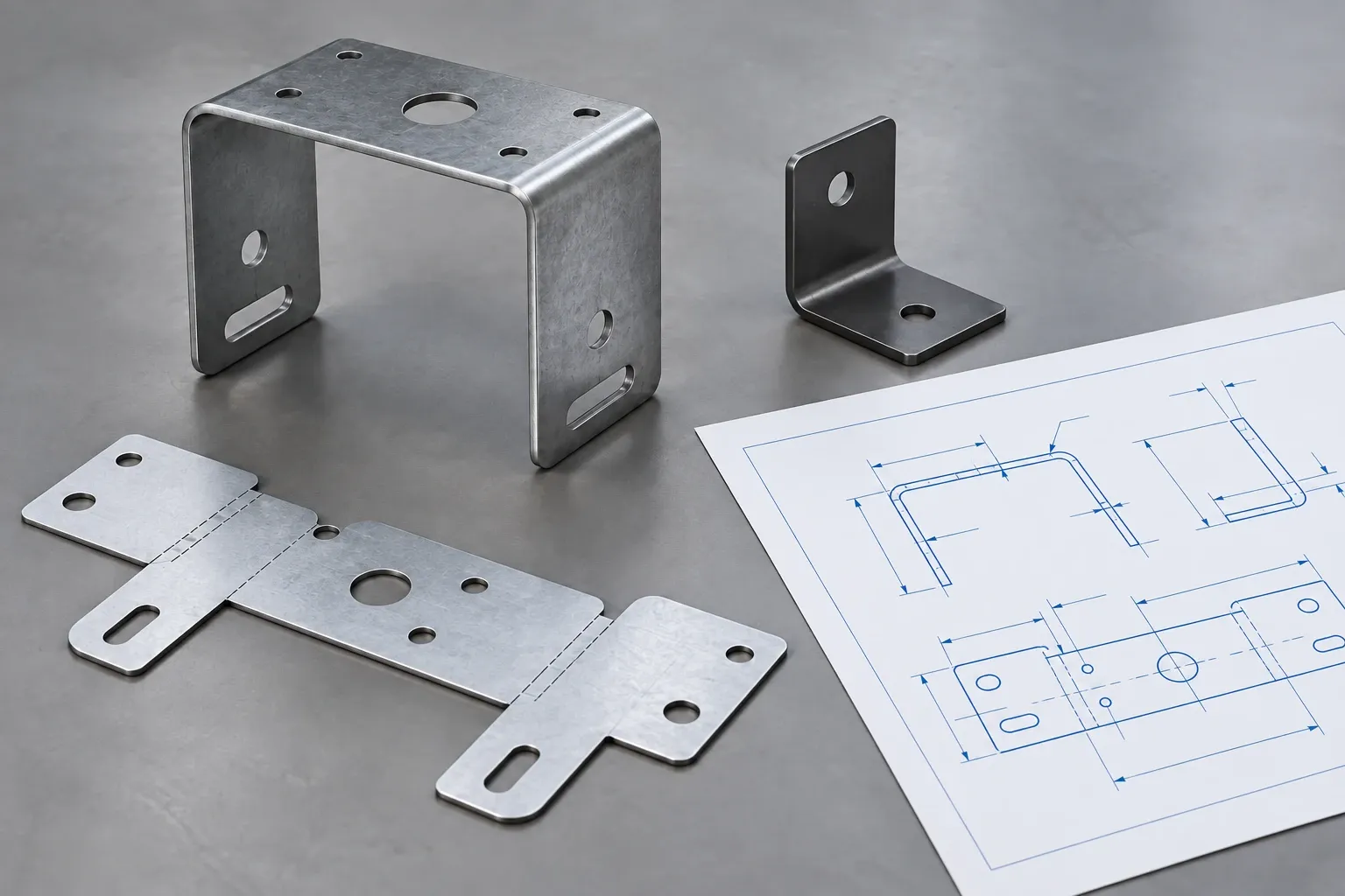
Functional dimensions should be defined on the finished bracket, especially when mounting holes or reference surfaces lie across one or more bends.A bracket can be cut exactly to its flat pattern and still miss the assembly after forming. The usual problem is not the outline of the blank. It is the finished relationship between mounting faces, holes, slots and offsets on different sides of a bend.
For a useful quotation, define the bracket in its delivered condition. Mark the surfaces that locate it in the assembly, dimension critical holes and slots from those references, state which angles or offsets matter after bending, and identify any dimensions that apply after welding, hardware installation or finishing. A flat DXF can support manufacturing review, but it should not be the only definition of fit.
Quote the Formed Bracket, Not Only the Flat Blank
A flat pattern answers a manufacturing question: what shape is cut before the part is formed? The buyer’s assembly asks a different question: where will the finished mounting features be after forming?
Material thickness, bend radius, tooling and bend sequence all influence the final relationship between flanges. That does not make the flat pattern unimportant. It means the RFQ must state what role the file plays.
If you send a DXF or DWG, identify it as either a controlled file or a manufacturing reference. The 2D drawing, formed STEP model and flat pattern also need matching revisions. If one file shows a different bend, hole or material thickness, the quotation engineer cannot know which condition to price without clarification.
The controlled drawing should contain requirements that a solid model does not reliably communicate on its own: material, thickness, finished tolerances, bend requirements, finish, inspection points and revision status.
Use the Assembly to Choose the Measurement References
Start with the way the bracket is installed. A base face may seat against a frame, one hole may locate the part, and a slot may allow adjustment. These features are better measurement references than a convenient outside edge that has no role in the assembly.
What the assembly needs | What the drawing should control |
|---|---|
A base sits against a panel | The finished contact face and critical dimensions measured from it |
Holes on two flanges align with mating hardware | The finished hole relationship across the bends |
A flange positions a sensor or component | The after-bend height, offset or angle that sets its location |
A coated surface still has to fit or conduct | Masking, final clearance and surfaces that must remain uncoated |
If a datum system is used, select datum features that represent the mounting condition. If formal GD&T is unnecessary, the same principle still applies: dimensions need clear origins, and the drawing must show which relationships are functional.
This is also where a generic all-over tolerance can cause trouble. Tight control on every cut edge may add cost without protecting the assembly, while the cross-bend dimension that actually controls fit remains unclear.
Features Across a Bend Need an Explicit Finished Relationship
Consider a U-shaped bracket with one mounting hole on each upright flange. Dimensioning both holes from separate flat-blank edges may fully define the cut file, but it does not necessarily state the hole-to-hole relationship required by the mating assembly after two bends.
For this type of part, the drawing may need to control the finished distance between the mounting features, their position from the seated base, or both. The correct method depends on how the bracket is located and inspected. The supplier should not have to infer that decision.
The same issue appears with:
- a slot on one flange that must align with a hole on another;
- a hole near a bend whose final shape or position affects assembly;
- an offset bracket that establishes two mounting planes;
- a formed tab that must clear a fastener, cable or neighbouring component.
There is no universal hole-to-bend rule for every material, thickness and tooling setup. When a nearby feature is critical, flag it for manufacturability review instead of relying on a generic design-guide number.
Any proposal to move a hole, change it to a slot or alter a bend belongs with the customer’s responsible engineer. DFM review can explain the manufacturing concern, but it does not approve a design change.
State How the Finished Dimension Will Be Accepted
An angle callout and a flange-height dimension do not always describe the same acceptance decision. Before releasing the drawing, decide which result protects the assembly.
If the flange angle is functional, control the angle and identify its reference. If the actual requirement is the location of a mounting surface, control that finished offset or height. Where several bends contribute to one relationship, show the final functional dimension instead of expecting the inspector to reconstruct the intent from the flat pattern.
The inspection condition matters too. A thin bracket measured in its free state may not give the same result as the bracket seated against its mounting references. If a critical dimension must be checked while restrained, on a surface plate or with a project-specific gauge, state that condition in the drawing or inspection requirement.
Avoid making a calculated K-factor or developed blank the only acceptance requirement unless your engineering process intentionally controls it. The delivered bracket should normally be accepted against the approved finished geometry and drawing requirements.
Include Hardware, Welding and Finish in the Final Condition
The quoted part is not fully defined if the drawing covers only cutting and bending while the purchase also requires installed hardware, welding or a finished surface.
YSBK supplies laser-cut and bent sheet metal parts from customer-approved drawings. The quoted scope can include TIG or spot welding, press-fit nuts or studs, powder coating, aluminum anodizing, passivation, brushed finishing and sandblasting when specified.
Show where hardware is installed and how it is oriented. Mark weld locations and any faces that must remain clear. For finishes, identify the finish type, relevant appearance requirement, visible surfaces and any threads, holes, grounding points or contact areas that require masking.
A photograph can clarify an appearance requirement, but it cannot replace the controlled finish specification. If a clearance or mounting dimension applies after coating or welding, state that directly.
Match the Inspection Request to the Features That Matter
For bent sheet metal parts, YSBK uses calipers, height gauges, angle gauges and a surface plate for agreed basic dimensional checks. A simple project-specific assembly gauge can also be arranged, with its scope confirmed before order placement.
YSBK does not have in-house CMM or optical measuring equipment. A CMM report is therefore not a default deliverable. If purchasing or quality requires a dimensional record, identify the dimensions to report, the number of parts to check and the required document format during the RFQ.
The available material scope includes SPCC and Q235 carbon steel, 304 and 316 stainless steel, and 5052 and 6061 aluminum. The normal sheet-thickness review range is 0.8 mm to 12 mm. Work outside that range requires separate quotation review.
This is the supply and inspection scope for this service, not a universal tolerance guarantee. The achievable result still depends on the submitted geometry, material, thickness, bend arrangement and measurement method. Inspection confirms the agreed drawing features; it does not validate the customer’s complete assembly, load case, safety requirement or field performance.
Send a Package That Defines the Delivered Bracket
Before requesting a quotation, make sure the package contains:
- the current controlled 2D drawing and matching formed STEP model;
- the flat-pattern file, if useful, identified as controlled or reference;
- part number, revision and quantity;
- exact material grade and nominal sheet thickness;
- mounting references and critical dimensions that apply after bending;
- controlled bend angles, radii or flange dimensions where they affect acceptance;
- hardware, welding, marking, finish and masking requirements;
- required inspection dimensions, records or gauge conditions;
- the requested delivery date.
When quoting multiple brackets together, include a parts list mapping each part number to its revision, material grade, sheet thickness and quantity. Requirements shown on one drawing should not be assumed to apply to every item.
For projects already defined by customer-approved files, review the scope for custom sheet metal brackets. Email is the preferred channel for the complete drawing package. The website form can be used to start the conversation before CAD files are exchanged by email.
YSBK’s DFM & Quotation Engineer reviews the package for completeness, initial manufacturability and quotation inputs. The first response may identify a missing finished-state dimension, a revision conflict or an inspection requirement that needs confirmation. This review is not approval of the bracket design and does not commit either party to production.