Manufacturing Process Guides
Vacuum Casting Design Guidelines: Wall Thickness, Draft and Undercuts for Urethane Parts
Review resin selection, walls, draft, undercuts, inserts, appearance, tolerances and mold planning before releasing urethane parts for vacuum casting.
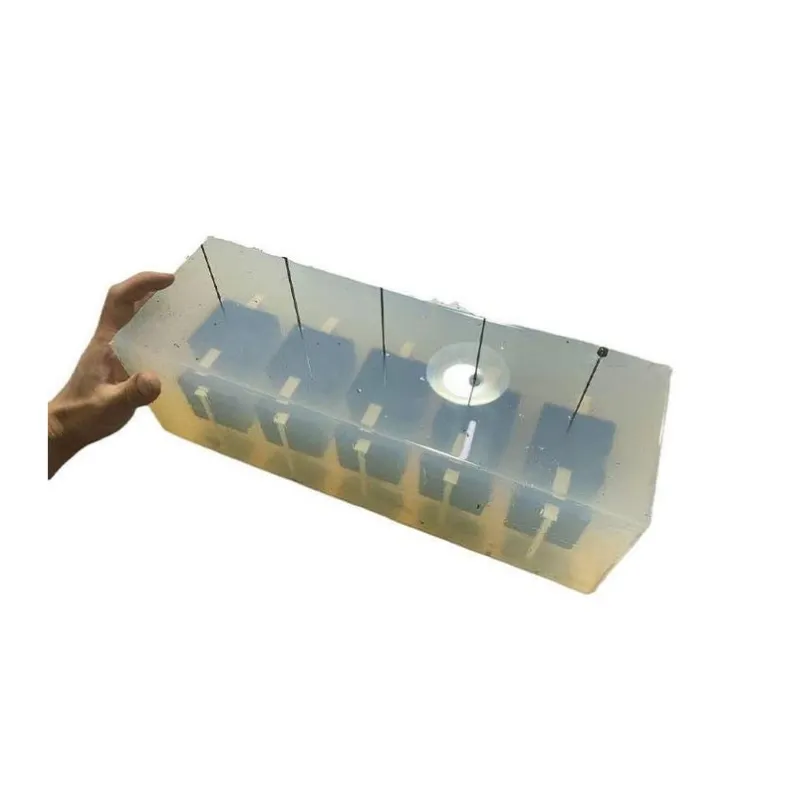
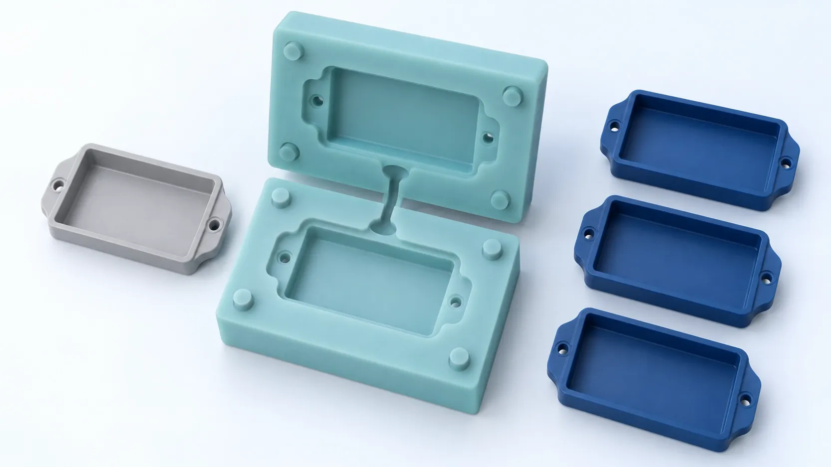
A vacuum-cast part should be reviewed against its material, geometry and acceptance requirements before the master and silicone mold are released. A flexible mold can help with some features, but it does not make every undercut releasable or every thin wall practical.
For an engineer, the review must establish whether the part can fill, cure, release and perform its intended function. For a buyer, it must make the quoted scope clear: master preparation, molds, finishing, inserts, inspection and any replacement tooling. For a first-time customer, it should identify the decisions needed before manufacturing begins.
Use the following checks to prepare that discussion. They are review questions, not universal wall limits, draft angles or tolerance guarantees.
1. Select an Identifiable Resin, Not Just an “ABS-Like” Label
“ABS-like,” “PP-like” and similar descriptions can help start a material discussion. They do not establish that a cast polyurethane has all the properties of the named thermoplastic.
Ask for the proposed resin manufacturer, product designation, current data sheet and delivered condition. Compare the properties relevant to the application, including the test method and specimen conditioning where applicable. If an alternative resin is proposed, review it before use.
Intended use | Requirement to define |
|---|---|
A flexible clip or hinge | Deflection, assembly method, repeated-use expectations and validation conditions |
A loaded boss or bracket | Load, duration, temperature and allowable deformation |
A moving interface | Contact arrangement, wear or friction requirements and testing |
A visible cover | Color, texture, permitted defects and appearance reference |
A clear part | Transparency expectations, visible zones and acceptance method |
Do not infer hinge endurance from a “PP-like” description, or wear performance from “POM-like.” If those functions matter, define and test them on the selected design and material.
A Real Data-Sheet Example: Why Conditions Matter
Sika's published typical data for SikaBiresin PX223 HT illustrates the level of identification needed:
Published item | Listed condition or value |
|---|---|
System | Two-component vacuum-casting polyurethane |
Maximum casting thickness | 10 mm |
Demolding time | 60 minutes for 3 mm at 70 °C |
Flexural modulus | 2,300 MPa, with the stated cure condition |
Heat deflection temperature | 110 °C under ISO 75A, with the stated cure condition |
Cure condition attached to those mechanical/thermal values | 100 °C for 1 hour plus 110 °C for 12 hours |
These are manufacturer data, not YSBK capability or stock claims. They do not establish a minimum wall, a complete production cycle, a continuous service-temperature rating or suitability for your assembly. Check the current Sika product data and processing information.
2. Review Wall Sections in the Context of the Whole Part
Mark nominal walls, local minimum sections, heavy junctions and abrupt transitions on a section view. Ask the supplier to assess them together with the selected resin, flow path and processing plan.
Do not treat a material's maximum casting thickness as a recommended nominal wall. Likewise, a small thin feature that can be filled does not prove that a long thin panel can be cast, handled and used successfully.
Where practical, compare gradual transitions and cored or rib-supported geometry with a heavy solid feature. Review the effect on stiffness, fastener support and appearance before approving a change. Reducing mass may help address a risk; it does not guarantee the absence of shrinkage, voids or surface distortion.
Location to review | Question to answer |
|---|---|
Thin wall at the end of a long flow path | How will filling and air escape be addressed? |
Boss behind a visible face | Can the geometry change without compromising assembly strength? |
Thick-to-thin junction | What processing and dimensional risks need evaluation? |
Large flat panel | What support, curing and inspection approach is proposed? |
Fine ribs or small details | Can they be filled and released without unacceptable damage? |
The useful output is an approved geometry and a list of remaining validation requirements, rather than a drawing marked “uniform walls” without a review.
3. Resolve Draft, Undercuts and the Demolding Sequence Together
Identify long walls, reverse features, narrow slots, sharp transitions and flexible clips. Ask the mold maker to explain the proposed release direction and mold construction before assuming silicone flexibility will solve the geometry.
The solution may involve draft, a different parting arrangement, removable elements, separate components or a design change. A two-half mold is not the only possible arrangement, and it should not be assumed before review.
Item | What to agree |
|---|---|
Draft | Where it is needed, proposed direction and effect on mating dimensions |
Undercut | Proposed release sequence and risk to the part and mold |
Parting line | Permitted location, mismatch and visible witness requirements |
Gate and vent locations | Permitted positions and acceptable trimming marks |
Fragile feature | Handling, demolding and any functional verification needed |
Do not place an unreviewed parting line or trimming mark on a sealing interface, locating feature or important visible surface. If no convenient location exists, resolve the tradeoff with the design owner.
Review changes before committing to the master where possible. Early changes can reduce rework, but engineering review and redesign are not automatically free.
4. Define Bosses, Fasteners and Inserts as an Assembly
A boss should be reviewed for its wall sections, available material around the fastening feature and the loads introduced during assembly and use. Coring or adding ribs is a design option, not an automatic cure for every defect.
For an insert, identify the manufacturer and complete part number, thread, material, installed position and required projection. Ask the supplier to propose a compatible installation method and supporting geometry.
Cast-in and post-installed approaches need separate review. Do not assume that an insert intended for a thermoplastic or a generic press-fit operation is suitable for a cured polyurethane boss. Review the insert maker's requirements and validate the actual resin-and-boss arrangement.
State any assembly torque, pull-out, rotation-resistance or repeated-assembly requirements and how they will be verified. Avoid claiming retention based only on the presence of knurls or another visible insert feature.
If inserts are cast in place, clarify positioning, protection of threads and required inspection. If installed afterward, define the method, acceptance requirements and responsibility for the operation.
5. Approve the Master and the Delivered Appearance Separately
Agree the master revision, preparation and approval scope before mold manufacture. Identify visible surfaces, intended texture, logos and lettering, together with any acceptable parting, gate or vent witnesses.
The master is an important reference, but it is not proof that every delivered casting will be acceptable. Also review trimming, mold condition, coloring, painting or other finishing included in the quotation.
If a finished sample is required, define what it approves: appearance, fit, dimensions or function. Record its identity and acceptance limits. Decide whether production must wait for approval; do not assume that a sample automatically creates a manufacturing hold point.
For markings, state whether they are molded or applied later, and identify the required location and legibility. Discuss small details before preparing an expensive cosmetic master.
6. Specify Dimensions and Inspection Conditions
Mark critical dimensions and references on a drawing. State the requirements for the remaining geometry through an agreed tolerance scheme rather than writing “standard cast tolerance” without identifying what that means.
For flexible or distortion-sensitive parts, clarify the measurement condition: support, restraint, temperature, conditioning and whether the part is checked free or assembled, as relevant. Define the finished state after any required cure, finishing and insert installation.
A fit-critical hole may need a specifically reviewed secondary operation. If so, identify its scope and how the workpiece will be located and supported. Do not assume that a cast pilot feature establishes an accurate final hole position.
Ask which dimensions are checked, the coverage and method, and what records are included. See the vacuum casting tolerance guide for the related discussion; the approved part requirements still govern the order.
7. Plan Mold Quantity, Replacement and Repeat Orders
Ask how the supplier intends to deliver the required quantity of accepted parts. The number of castings expected from one silicone mold should be a project-specific planning assumption, not a universal guarantee.
Purchasing question | What the quotation should clarify |
|---|---|
How many molds are included? | Initial tooling scope and any parallel production plan |
What if a mold becomes unsuitable? | Replacement responsibility, cost assumptions and delivery impact |
What quantity is being purchased? | Accepted finished parts, separately from samples or setup pieces |
What controls repeat orders? | Master revision, resin identity and acceptance requirements |
What will be retained? | Agreed master and mold storage terms, if offered |
Do not presume that storage guarantees a mold remains reusable indefinitely. For repeat orders, confirm the condition and availability of retained tooling and resolve whether new tooling or sample approval is needed.
Worked Example: A 30-Piece Sensor Cover Review
This is a hypothetical planning example, not a customer delivery record or a confirmed production method.
A buyer requests 30 covers with a visible front face, a clip, two threaded inserts and a fit-critical opening. The first brief says “ABS-like urethane.” That description leaves the material, release plan, insert method and acceptance requirements unresolved.
Open issue | Evidence or decision needed before release |
|---|---|
Resin | Named product, relevant data-sheet conditions and functional validation requirements |
Boss behind the front face | Reviewed geometry change and effect on appearance and assembly |
Clip and undercut | Release plan, permitted witnesses and clip test requirements |
Two inserts | Exact hardware, installation method, location and retention acceptance |
Opening | Dimension, references and measurement condition |
Delivery | Mold scope, sample approval point and 30 accepted-part requirement |
If the team considers reducing a heavy boss or adding draft, it must check how those changes affect the assembled product. If the clip cannot be released or used reliably, a separate component or another route may need comparison.
Release the approved design and manufacturing scope after those decisions. Review the agreed first-part evidence before authorizing further production where a hold point is specified. The review reduces uncertainty; it does not prove the mold will succeed on the first attempt.
What to Send for a Useful Casting Review
Provide the CAD model, drawing revision, quantity, delivery date, intended use and proposed resin or material requirements. Identify critical dimensions, visible surfaces, inserts, assembly loads and any relevant test requirements.
Ask the supplier to return proposed geometry changes, mold and release assumptions, material identity, master preparation, finishing, inspection scope and unresolved exceptions. Define who approves each change and how the approved files are released.
If the route itself is still undecided, compare 3D printing and vacuum casting or vacuum casting and CNC machining against the same requirements. When you contact YSBK, describe the function and open questions as well as the part's shape.